
Model co-ordination
We’re starting with a topic that can be one of the biggest obstacles to success on a BIM project – coordinating BIM data, which is a common project requirement.
By ‘coordinating’ I mean accurately compiling geometric BIM models from various sources into one single source. This is also known as creating a ‘federated model’, although there’s always arguments about the definition of that term.
BEPs
BIM Execution Plans (BEPs) are project documents that define how the client’s BIM requirements are to be met, who is responsible for delivery and the timescales for this delivery. If you’re not familiar with BEPs, click here to download the relevant PAS standard
The PAS1192 document makes several references to coordination of models for clash detection, but we can’t rely on the PAS docs to tell us how to actually achieve this.
We have completed many projects where coordination of BIM data has been difficult, either because of software or skill limitations. This can lead to delays in delivery and possibly the erosion of fees. Below is the first of some suggested BEP addendums that will help you avoid the common pitfalls we see around successful coordination of BIM data, especially when lots of different BIM software types are being used..

X/Y Co-ordination
Some BIM systems can understand global coordinates, others cannot – this can lead to a problem with X/Y coordination. To prevent coordination issues we always lobby for the addition of the following clauses to our BEPs:
1: Examine capability statements to ascertain what BIM systems are being used, and identify any potential limitations. This does require a certain level of experience with the software and can be made easier by requesting sample BIM data for analysis.
2: If limitations do exist (a recurring example of this is if a particular BIM software cannot handle global coordinates) then alternatives have to be agreed upon.
Project Zero
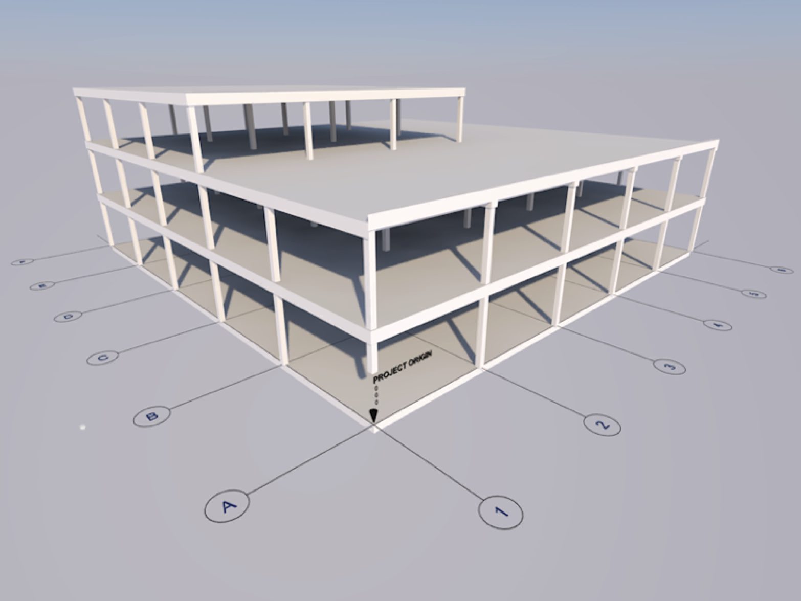
A popular workaround is to define the project zero as a grid intersection and use this as a point for coordination. Every BIM system we’ve come across has a project zero, so we recommend it.
In this example the gridline intersection A1 has been marked as project zero. The actual global coordinate at this point is then noted in the BEP.
Model data can be linked into a separate site file using this coordinate as a reference when setting out.
Our next blog...
Will look at Z co-ordination – preventing issues with Z axis co-ordination.